
A P5 picture has no discernible noise.
Click on the picture for a large version.
|
The "P" system, like other signal reporting systems, are based on one's experience, sentiment, and understanding of the technology. This makes them subject to personal biases, as this story illustrates: Several years ago, I had the occasion to visit the shack of a local ATVer who had reported that he had received a "P5" signal from the repeater. While there, I saw a signal from the repeater (an ID screen) and observed that I though it was more of a "P3" picture. He pointed out (and demonstrated) that the quality of the picture he received from the repeater was on par with those from the local off-air television stations. He was the first to admit that his off-air antenna wasn't as good as it could be. To his credit, he did put good effort into making his ATV receive setup as good as it could be (and it was quite good - as the ATV repeater really was quite weak at his location.) |
Notes:
As in voice modes, there is a system of signal quality reporting for amateur video modes. Akin to the "Q" (quality) levels (as in "You are Q5 copy old man") the ratings go from P5 (perfect signal) to P0 (barely detectable signal.)
Interestingly, the "P" system takes into account only the thermal noise in the signal and not other types of signal degradation (i.e. multipath or QRM, or video/transmitter deficiencies) but these effects are often quantified as part of the signal quality expressed by the "P" system.
As are the "Q" signals, the "P" signals are very subjective. However, there is a descriptive basis for this reporting system. It is difficult, with still pictures, to accurately portray how "noisy" a picture actually is owing to the "averaging" effects of the eye and the brain, but I believe these descriptions to be close.
P5 signal:
"A P5 picture has no discernible noise."
Signal/Noise ratio of >45
db, >1000 microvolt signal strength.
|
Working the the broadcast industry, I would consider a P5 picture to be one that has better than a 50 db signal-to-noise ratio (broadcasters often consider the "noise free" S/N ratio to be 60 db.) It is difficult to discern when noise in a picture is lower than 45-50 db without doing an A/B comparison and/or using test equipment.
A good quality consumer grade videotape recorder can just barely produce a 45-50 db S/N ratio (that goes for the newer digital consumer equipment, too...) and a consumer grade camera is typically in the 48-50 db S/N ratio range - and that's only when you have good (i.e. bright) lighting. (I might point out that the 45-48 db range corresponds with the best S/N you can get with an 8 bit digital representation.) For this reason, I would certainly be willing to give a 45 db S/N ratio amateur signal a "P5" rating.
Finally, almost no currently produced ATV gear can even approach the 45 db S/N range: Taking the PC Electronics TXA5, for example, while this is a "good" amateur-grade transmitter, its IMD alone is no better than the low 30 db region at best: This is especially evident when the aural carrier is set to a "normal" injection level. It is this "grunge" that takes such a signal down to a P4 right out of the antenna spigot. Even if the exciter produced "perfect" signals, the typical amateur grade power amplifier's intermodulation would produce enough noise to reduce the S/N to below "P5" range. It takes broadcast quality equipment throughout the entire transmitter chain to produce a transmitted P5 picture. (If you are using a PC Electronics or other exciter on your ATV repeater or home station look at The KD2BD ATV AM Video Modulator to see how you can improve your signal!)
Now considering that we are amateur radio operators, we aren't likely to have "broadcast quality" pictures emanating from our antenna. On the other hand, being an amateur radio operator does not provide an excuse for transmitting a rotten signal: One of the challenges is to do the best we can with what we have.
Therefore, in amateur service, I would be more than willing to concede that a P5 picture is one that is "as good as it is going to get." That is, you see the signal and it looks as good as it possibly could even if it was much stronger (i.e. you aren't picking up noise because it's weak.)
P4 signal:
"A P4 picture is very slightly noisy."
Signal/Noise ratio of 35-45
db, 200-1000 microvolt signal strength.
 |
In reality, most of the best quality images on ATV are, in reality, P4 pictures. A P4 picture is considered by most who view it as being perfectly acceptable. (According to the Cable Television and Broadcast industries, a video S/N ratio of 40db is what the "average" person considers to be "acceptably noise-free.") A signal of this quality is what would be considered to be "good" by the average viewer of broadcast television. It is a simple fact that most amateurs will simply not have the resources to be able to radiate a strong enough signal to attain that goal of a "visibly noise-free picture." This is no fault of the amateur operator, but rather one of the properties of Amplitude Modulation.
In a P4 picture one can see a bit of noise - most notably in the chroma (color.) This amount of noise is not distracting and the noise disappears, for the most part, when one retreats from the television screen to the couch across the room.
When considering the quality of a picture, the size of the television screen makes a lot of difference: A picture that looks noisy on a large television screen may look perfectly fine on a small one - particularly a small LCD screen. This effect is largely a result of the fact that noise shows up most prominently in the high frequency components of the video (where the least amount of video energy is.) These same high frequency components correspond to the amount of detail in a picture. Since a small screen cannot represent as much detail the noise is less visible. LCD displays have another property that tends to mask noise: They are comparatively slow to respond to picture changes and thus they tend to "average" out received noise.
The moral of the story? Remember that the "P" signal report that you give will vary with the size of picture you are looking at. If you are giving or receiving a signal report that is based on the quality observed on a small CRT or any LCD screen you can safely assume that the display is making the received signal look better than it really is.
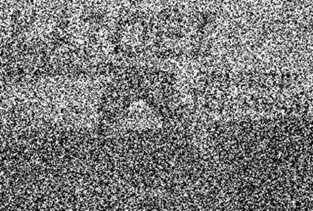
P3 signal:
"A P3 picture is 'somewhat' noisy."
Signal/Noise ratio of 20-35
db, 50-200 microvolt signal strength.
 |
A P3 picture is one that is definitely noisy, but not too noisy. A P3 picture is about as noisy as it can be without the noise being annoying or obscuring some of the finer detail. (Does that make sense?)
First, a note about the noise in the pictures:
Noise that appears in video is essentially random and changes from
frame
to frame. This constantly changing noise is somewhat "averaged"
by
the brain as the picture is viewed. To demonstrate this to
yourself,
play a recording of some noisy video back a frame-at-a-time using your
VCR and you'll see that the frozen frame looks much worse than the
moving
video. (This is even true of video that you would not
consider to be noisy!) If you want to capture a single image from
an off-air source, the trick is to capture several (nearly) consecutive
frames (where there is relatively little movement) and average them
together
to reduce noise. For this reason, it is difficult to properly
represent
the noise of a moving image by a representation in a still image.
P2 signal:
"A P2 picture is definitely noisy."
Signal/Noise ratio of 8-20
db, 15-50 microvolt signal strength.
 |
A P2 signal is noisy enough to become tedious to watch and the finer details of the image are lost. The signal/noise ratio of a P2 signal is low enough that many televisions and monitors may not reliably display color and the sound just starts to get noisy, but this will depend on the receiver and the amount of aural carrier energy in the transmitted signal.
Additionally, the overall picture usually starts to "lighten" as a result of the noise energy. This is a result of the fact that AM transmitted NTSC video uses downward modulation: That is, dark area are represented by more transmitter power and lighter areas are represented by less power. Thus, with weak signals, the lighter areas of the picture (which are represented with less transmitter power) appear to be more noisy. This noise can often upset (or confuse) the DC restoration circuits in the monitor as well as confuse the sync circuits. Sometimes this can result in a signal that appears to be darker instead of lighter (on some monitors and with video capture devices in particular) as well as some "jittering" in the sync, causing horizontal or vertical instabilities in the received picture.
Since the finer details of a video image are represented by higher frequency, and since there is less high frequency energy in a typical video image( as compared to low frequency energy) it is these high frequency components that are the first to be overcome by noise. Finally, since the color information comprises a relatively low percentage of the total transmitted energy of a video signal it is also one of the early casualties a weak signal.
P1 signal:
"I can barely see your ID, OM..."
Signal/Noise ratio of 3-8
db, 5-15 microvolt signal strength.
 |
The P1 signal is barely capable of yielding much useful information. You can hope that the other station is transmitting a VERY LARGE ID for only the largest elements of the picture (those with the lowest frequency components) are going to survive. If you stare at the image long enough, you can usually use your "gray cell integrator" (i.e. the brain) to "average" out some of the noise and the larger features of the image may be discernible. The sound is often lost or very noisy by the time the signal is as weak as a P1.
A signal strength that would yield a perfectly full quieting FM voice signal (and then some...) results in a barely perceptible image. This is a result of the wide bandwidth (6 MHz) of a video receiver as compared with the relatively narrow bandwidth (15 KHz) of a narrowband FM receiver. This 400-fold difference in bandwidth translates directly to an approximate 26 db signal strength disadvantage for the TV signal.
Furthermore, the wide bandwidth of a video signal means that it is at a thermal disadvantage to an FM signal: The 6 MHz video bandwidth gathers enough signal to be be equal to an approximate a microvolt or two from thermal noise alone. This is true for any TV system in which the receiving antenna's pattern includes the earth itself, as the earth comprises a (nominal) 280-300 Kelvin noise source - a noise temperature that far exceeds modern GaAsFET preamplifiers.
P0 signal:
"Is there really a signal there?"
Signal/Noise ratio of <3
db, <5 microvolt signal strength.
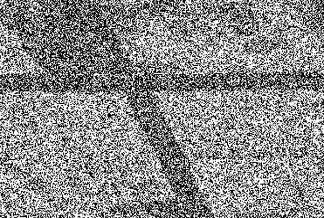 |
A P0 signal is the weakest that you can detect (but that doesn't mean that you can tell what it is...) What good is a P0 signal? What can this tell us about anything? Can a useful signal have a negative signal/noise ratio?
The answer to these three questions is "yes." Sort of.
The picture above shows what such a signal may look like. Actually, it looks a bit better than a typical P0 picture for demonstration purposes. For all practical purposes, all detail is lost and only the sync bars (both horizontal and vertical) are visible as the receiver struggles to lock onto them.
While the bandwidth of a video signal is 6 MHz, one of the characteristics of an AM demodulator (such as that in a video receiver) allows that if, post demodulation, a narrowband detector is used, one can discern signal components within that 6 MHz bandwidth. As it turns out, the sync signals (the horizontal, but especially the vertical) carry the peaks of the energy of the video signal. Not only this, but since it known precisely what baseband frequencies the sync signals comprise, and the fact that the sync circuits themselves have fairly narrow bandwidths, it is possible that a television will lock onto sync without recovering any discernible video. It is this property that allows sync detection from a signal that has an otherwise negative signal/noise ratio.
So, with a P0 signal you can sometimes acquire sync from a video signal, or, more likely, you will see very weak sync bars roll through the picture occasionally. I could typically "detect" sync bars on signals at about 1 microvolt on an "average" modern television set.
A P0 signal can be useful for determining the mere presence of a
video
signal, or it can be used as a starting point for improving or
optimizing
your receive system: It is much easier to discern small
improvements
in a P0 or P1 signal than in a P3, or P4 signal. For example, if
you are using a set of rabbit ear antennas and you can detect a P0 or
P1
signal, you can probably assure yourself that if you were to install a
decent outside antenna system you would get at least a P3. Of
course,
your mileage may vary.
|
A baseband signal is the signal that is modulated on the carrier for transmitting. In the case of video, this would include not only the entire video signal but the aural (audio) subcarrier as well. A typical video receiver demodulates the entire television signal (video and sound) as just one signal. After demodulation, the video and audio are treated separately. |
For any questions, comments, or blame, you can email
me and complain...
This page last updated on 20021024
Return to the Utah ATV Home Page...